SOLAR TREATMENT OF WATER (SOLWATER)
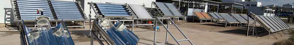
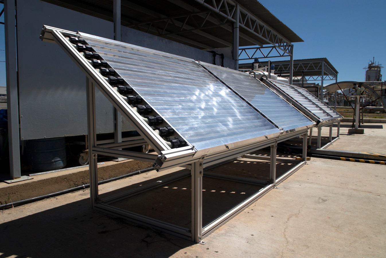
Several CPC pilot plants have been installed at PSA facilities built by modules that can be connected in series. Each module consists of several photoreactors (borosilicate glass tubes) placed in the focal point of an anodized aluminium mirror with a Compound Parabolic Collector (CPC) shape and placed on a platform titled 37° from the horizontal to maximize the global solar collection of photons through the year in the PSA location.
In addition, the pilot plants are equipped with added systems for different purposes, for example sedimentation tanks (for catalyst recovery), heating and cooling systems for temperature control during the experiments, coupling with other treatment technologies like biotreatment, ozonation, etc. Moreover, these plants also have different technical characteristics including illuminated surfaces, treatment volume, photoreactor diameter, etc. Most of the CPC pilot plants of the TSA are described below (Figure 1):
- CPC SOLEX photo reactor prototype (Figure1a): two twin reactors developed for specific treatment applications through solar photo-Fenton. Each prototype consists of two CPC units connected, with 32 mm borosilicate glass tubes, 3 m2 of illuminated surface, with 40 and 22 L of a total and illuminated water volume, respectively. It also has several sounding lines that allow us to monitor dissolved oxygen (DO) and temperature (Tª).
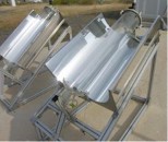
- CPC CADOX photo reactor prototype (Figure 1b): it consists of four CPC units (50 mm tube diameter) with a total gathering surface of 4 m2 and a water treatment volume of 75 L of which 45 L are illuminated. This prototype has been designed and built to connect it to an ozonization system (50 L) and treatment through biological oxidation. It also has a pH, Tª, DO, H2O2, O3 and water Tª control and reactive dosage monitoring system. Besides, and connected to this photo-reactor, there is a biological water treatment system consisting of three tanks: a 165 L conical tank for wastewater conditioning, a 100 L conical recirculation tank and a 170 L flat-bottom fixed-bed aerobic biological reactor (filled with 90-95 L of Pall®Ring polypropylene supports to be colonized by active sludge).
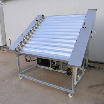
- NOVO75 photo reactor prototype (Figure 1c): solar reactor prototype with a different mirror set-up that allows increasing the illuminated water volume. It consists of twelve 75 mm diameter borosilicate glass tubes connected in series, with a 2 m2 illuminated surface, 74 L total volume with 68.5 L illuminated volume. It is equipped with Tª, DO and pH sounding lines, as well as a Tª control system and oxygen boost in water. Currently, this prototype has been modified in order to fit in an ozonization experimental plant.
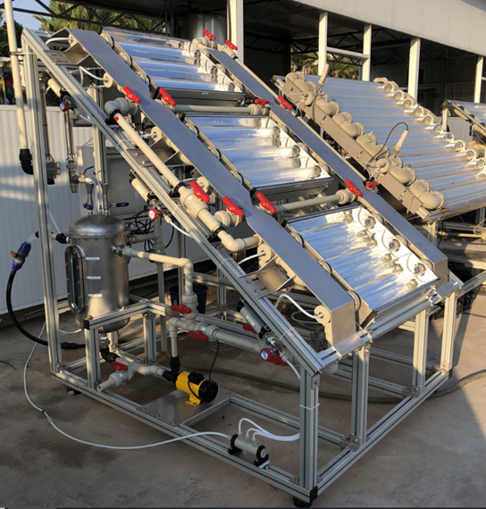
- FITOSOL-CPC prototype (Figure 1d): two experimental plants that consist of a 4.5 m2 gathering area CPC type solar reactor (37º inclined) (60 L total volume, 45 L illuminated volume) and a post-treatment through sedimentation in a conical base tank plant (100 L). Both plants are equipped with pH and dissolved oxygen sounding lines (DO, Multi CRI-SON 44) connected to a data memory automatic system. It also has a Tª control system (heat and refrigeration) and a few airflow points and DO measurements.
- ELECTROX-CPC: (Figure 1e) A 2 m2 CPC collector with 10 borosilicate glass tubes (50 mm diameter), an illuminated volume of 25 L and a total volume of 40 L is connected to four electro-cells for experimental research on electro-photo-Fenton processes for decontamination and disinfection of water.
 b)
b)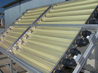
c)
 d)
d) 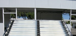 e)
e)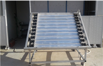
- O3-CPC (Figure 2a): It consists of three solar CPC modules whose design allows to work with them individually or connected in series with a common tank (12, 17 and 22 L for one, two or three in series). Each CPC module has three 50 mm borosilicate glass tubes (700mm length and ca. 650mm illuminated) with stainless steel gas diffusers (2 µm) at the ends, 0.32 m2 of illuminated surface and 3.8 L of illuminated volume. Moreover, it includes online monitoring of pH, T, dissolve O3 (model UV-106-W) and DO as well as a thermo-catalytic ozone destructor.
- 25 L-CPC (Figure 2b): it consists of two CPC type independent plants set up on a 37º inclined platform. Each prototype has 5 borosilicate glass tubes connected in series (50 mm external diameter), with a 1 m2 illuminated surface, 25 L total volume (11.25 L illuminated volume). One of them with a configuration that allows to work in flow or static conditions as well as allow to adapt it at different water volumes.
- 25L SODIS-CPC (Figure 2c): two CPC type plants without water recirculation, only with one borosilicate glass tube (200 mm diameter), 0.58 m2 illuminated surface and 25 L of total and illuminated volume, designed as a low-cost system for solar disinfection and titled at different inclination angles to match the local latitudes of PSA and African countries where the solar disinfection technology should be implemented.
- CPC versus U (Figure 2d): It consists of two tanks with 192 and 92.5 L of capacity connected to two independent photo-reactors of 2 m2 with different mirror geometries (CPC and type U) to assess solar disinfection efficiency and low-cost reactors design and both with the total volume irradiated (35 and 52 L in the CPC and U, respectively). The plant is completely automatic and consists of several Tª and UVA radiation sensors. It also has several systems to analyse the thermal effect through a solar thermal panel that allows raising the water Tª before going through the photo-reactors, a water recirculation system in each photoreactor and airflow points.
 b)
b)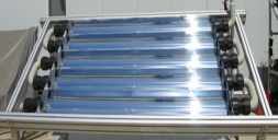
c)
 d)
d)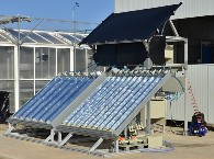
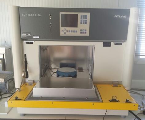
Besides, and apart from the option of escalating the described solar experimental plants, other two lamp irradiation system are installed:
- Two solar simulators XLS+ (Figure 3a) provided with xenon lamps (>290 nm, UV filter) for simulating external solar radiation in small-scale water decontamination and disinfection experiments. In both systems, the radiation intensity can be modified and monitored as well as the temperature (cooling system, SUNCOOL).
- A UV-LED lab system (Figure 3b) Photolab LED, APRIA Systems S.L.) consisting of a collimation system provided with 4 LED lamps at the different regions of the irradiation spectrum (UV-C (λmax = 275 nm), UV-B (λmax = 300 nm), UV-A (λmax = 370 nm) and VIS (λmax = 300 nm) to perform photochemical and photo-catalytic lab-scale experiments studying the influence of the irradiation region. The reactor allows to perform water treatment experiments in Petri dishes containers (Ø= 5 cm, V ≈ 35 mL), is controlled by a console that allows the regulation of each LED by independent control systems (on/off and total radiated power selection) that allows to simultaneously working with the 4 LEDs installed (in different containers) and to control and monitor both, the temperature and the power consumption.
 b)
b)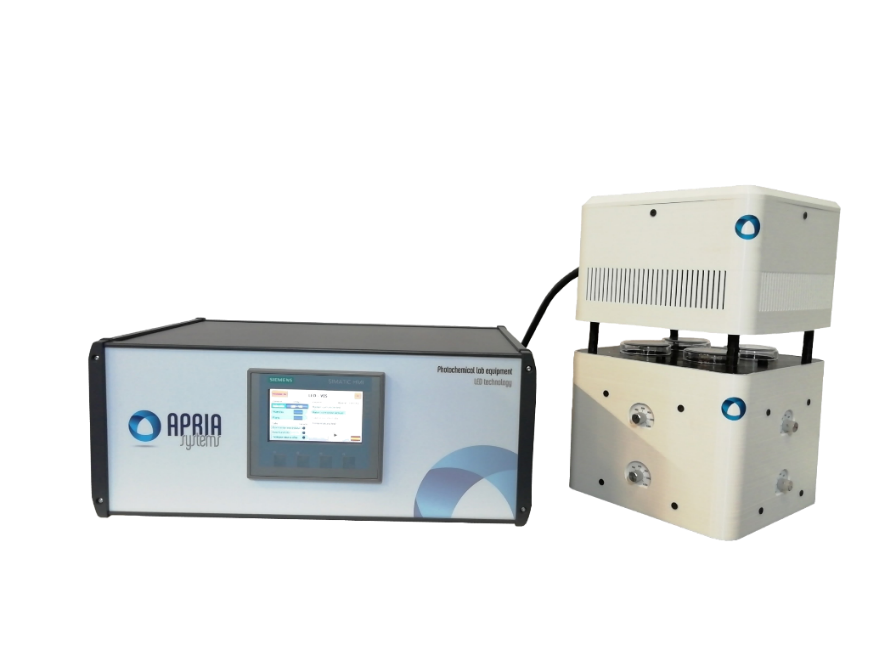
The experimental plants based on non-solar or hybrid (connection to solar and non-solar systems) advanced oxidation treatments are described below (Figure 4):
- UV-C pilot plants (Figure 4a), two UV-C experimental plants designed to treat and disinfect water for research and comparison with solar technologies. The first one has a common tank (200-250 L) integrated with two different systems: i) one with three UVC lamps modules connected in series (maximum flow: 25 m3/h, length of highest wave: 254 nm, maximum power: 400 J/m2, illuminated volume: 6.21 L and area: 0.338 m2), a flexible operation mode (1, 2 or 3 lamps and in recirculating batch mode or continuous flow mode), a dosage system of reactants (acid, base, and hydrogen peroxide/oxidant) and several sensors (pH, DO and UV transmittance sensors) and; ii) a unique UV-C module with three UV-C lamps (UV Lamp Dulcodes 3 x 230 LP, maximum flow: 86 m3/h, length of highest wave: 254 nm, maximum power: 3000 J/m2, illuminated volume: 97,6 L and area: 1.37 m2), equipped with seven transmittance sensors (specific design of this pilot-plant with 6 “extra” sensors, UVC-SE sensor-Opsytec Dr. Gröbel GmbH) and a flexible operation mode that allow working with 1, 2 or 3 lamps as well as to fit the lamps power level.
The second is a UV/filtration disinfection plant which consists of a UV-C lamp and a 25-micron filter to remove the microbiological contamination from tap water before carrying out the subsequent treatment of water.
- Photo-electro-Fenton plant (Figure 4b), consists of four undivided commercial electrochemical cells (Electro MP Cell from ElectroCell) connected to a Delta Electronika power supply and a water reservoir from which the electrochemical cells are connected with a CPC reactor (ELECTROX-CPC, Figure 1e).
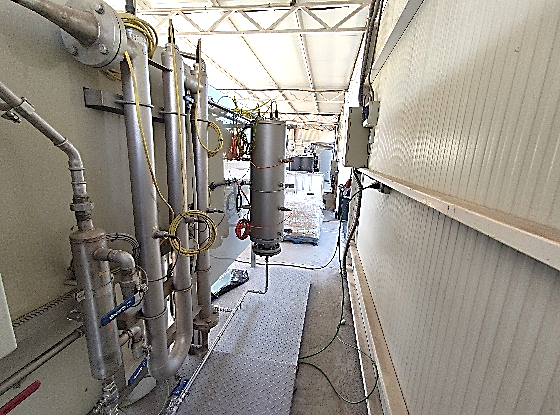
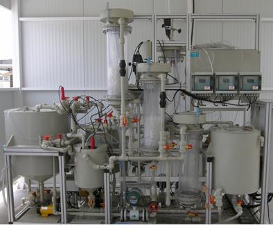
- Ozone plant (Figure 4c), consists of two different systems: a conventional contact column reactor (up to 580 L, titanium ozone diffusers) and a pressurized system with a total volume of 110 L that allows working in a nanobubble mode (high-pressure pump) and in a microbubbles mode by Venturi injection of ozone directly in the recirculation system of the tank or in a little intermediate tank (ca. 2.5 L). This reactor is equipped with an oxygen generator (Anseros SEP100), a flowmeter for inlet air regulation, an ozone generator (corona-discharge, Anseros COM-AD02, 44 g O3/Nm3 for a gas flow of 0.2 Nm3/h), two non-dispersive UV analysers (BMT 964) to measure inlet and outlet ozone concentration in the gas phase, a dissolved ozone sensor, a system for humidity elimination in the gas phase (outlet) a thermo-catalytic residual ozone destructor. This ozonization system works in a batch mode allowing its combination with other technologies such as CPC photoreactors, photocatalysis and the UV pilot plant.
 b)
b)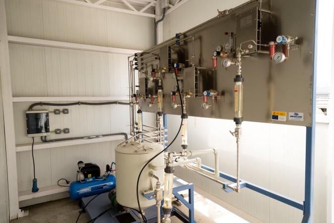 c)
c)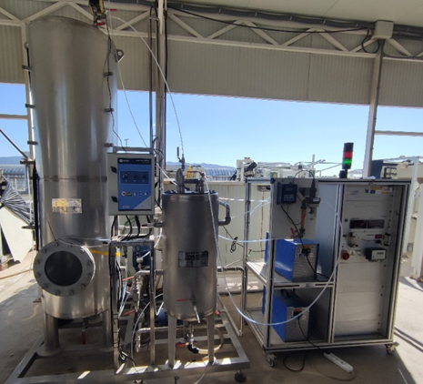
Moreover, two membrane systems are also installed to treat urban/industrial wastewater obtaining a clean water stream (permeate) and a rejected stream as a concentrate of contaminants (to reduce the contaminated water volume and consequently the solar CPC field required) or value-added products in a circular economy framework.
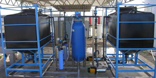
- Nanofiltration plant (Figure 5a) which consists of a 400 L feeding tank connected to three membranes frames (FILMTEC NF90-2540, polyamide thin-film composite) with a total surface area of 7.8 m2, connected in a way that can work in series or in parallel at 41 bar, 1.4 m3/h and 45°C of maximum pressure, flow and temperature, respectively. The system is completed with an automatic dosage of several reagents such as to control the pH value (2 to 11) allowing the cleaning and the separation of different compounds. This plant is automatized (electro-valves) and acquires different instrumentation signals (flow, pressure, conductivity, temperature, etc.) for controlling the required quality of the two streams generated (permeate and concentrate).
- Membrane distillation plant (Figure 5b) consists of a membrane distillation module integrated into a system consisting of two hydraulically separated loops, one for the hot solution and the other for the cooling solution and a 150L feeding tank (Qmax = 1.1 m3/h, T = 80°C). The control of the plant is automatized being the variables registered and allowing to work during 48h. The materials of the plant support its work in a wide pH range being also equipped with a pH regulation system. The system also has the option of using a 25L jacketed borosilicate crystallizer for recovery of the value-added compounds from the rejected stream.
 b)
b)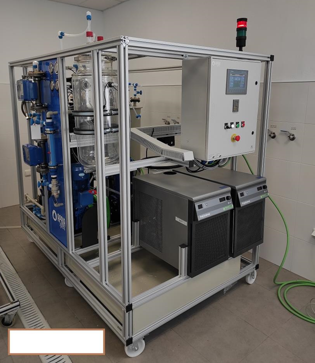
To treat industrial wastewater, a full treatment train is established, which usually consists of a pre-treatment step, an advanced oxidation treatment to enhance the biodegradability of the complex water matrix, a subsequent biological treatment and finally a tertiary treatment that allows its agricultural water reuse. For this aim, the facilities also count with:
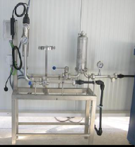
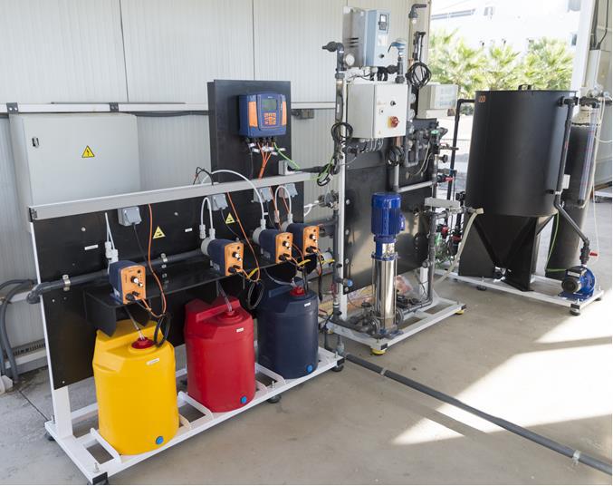
- A raw water pre-treatment plant (Figure 6a) based on physic-chemical processes: a coagulation-flocculation system and filtration step (sand filter and two microfilters of 25 and 5 µm) that allow working with a maximum water flow of 1m3/h.
- A biological pilot plant with a double depuration system (Figure 6b). This plant can be operated in continuous or in batch mode and consists of a 60 L feeding tank; three Immobilized Biomass Reactors (IBR) of 20-L each; and two Sequencing Batch Reactors (SBR) of 20-L each one. The second line of treatment consists of stirred type tank reactors (RTA) with 40 L total capacity (two 20 L RTA). All the reactors are inserted in the same unit and use the same reception tank (200 L) as well as data acquisition of three multimeters (pH and DO, M44 CRISON) and a SCADA system that monitors the main parameters and programmes the relays. Both processes can operate intermittently or continuously as well as independently or in combination.
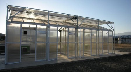
Finally, the treated industrial/urban wastewater is reused for in-vivo irrigation tests in an experimental greenhouse to grow crops in controlled conditions and study in-vivo the viability of reusing treated wastewater for irrigation.
- Experimental greenhouse (Figure 6c) of 30 m2, made of 10 mm polycarbonate thick with a shoulder height of 2.5 m and a roof slope of 40%. The chamber is divided into 4 independent and equal rooms (3 m2 x 2.5 m2). Each area is equipped with independent and automatized systems that control temperature, humidity, irrigation (automatic drip irrigation) and aeration (the roof slope of each area acts as windows) by using the Ambitrol® software. Moreover, the crop camera is equipped with a global solar radiometer for measuring the incident solar radiation connected to a cover on the top of each room which can be automatically folded and re-fold to reduce the incidence of irradiance.
b)
 c)
c)