
MDTF
Test-Bed for Solar Membrane Distillation Applications at Pilot-Scale
The installation is designed for evaluating solar thermal desalination applications. There are two solar fields of flat-plate collectors available: one of 20 m2 with two parallel rows of five collectors in series (Solaris CP1 Nova, by Solaris, Spain), and another one of 40 m2 with four large-aperture collectors in parallel (LBM 10HTF, by Wagner Solar, Spain). Both fields are connected to water storages of 1500 litres acting as heat buffers for thermal regulation and storage; they also have a distribution system which enables simultaneous connection of several units. The test-beds allow for a stationary heat supply using the thermal heat storage or for direct supply of solar energy without buffering. The installation is fully automated and monitored (temperatures and flows) and allows for heat flow regulation. The maximum thermal power is 7 kWth in one case and 14 kWth in the other, and hot water can be supplied with temperature up to about 90°C.
 b)
b)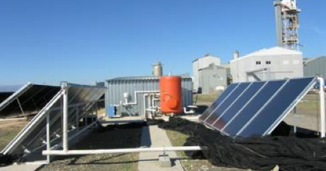
The installation has a separate water circuit that can be used for cooling (about 3.5 kWth) in the desalination units and as a device for supplying simulated seawater, with the possibility of working in an open or closed loop. In the latter case, both the distillate and brine flows are collected and mixed to be fed again into the desalination units after passing through a heat dissipation system. The installation currently operates with Membrane Distillation modules and has a wide range of different commercial and pre-commercial units from different commercial manufacturers. The list of MD modules that have been evaluated or are under evaluation is:
- Plate and frame airgap (AG) MD commercial modules from Scarab (total membrane area 2.8 m2).
- Two plate and frame permeate-gap (PG) MD prototypes from Keppel Seghers (both with total membrane area 9 m2), a compact one (M33) and another which is split in three separate modules connected in series for higher energy recovery (PT5).
- Spiral-wound PGMD commercial modules Oryx 150 from Solar Spring (10 m2).
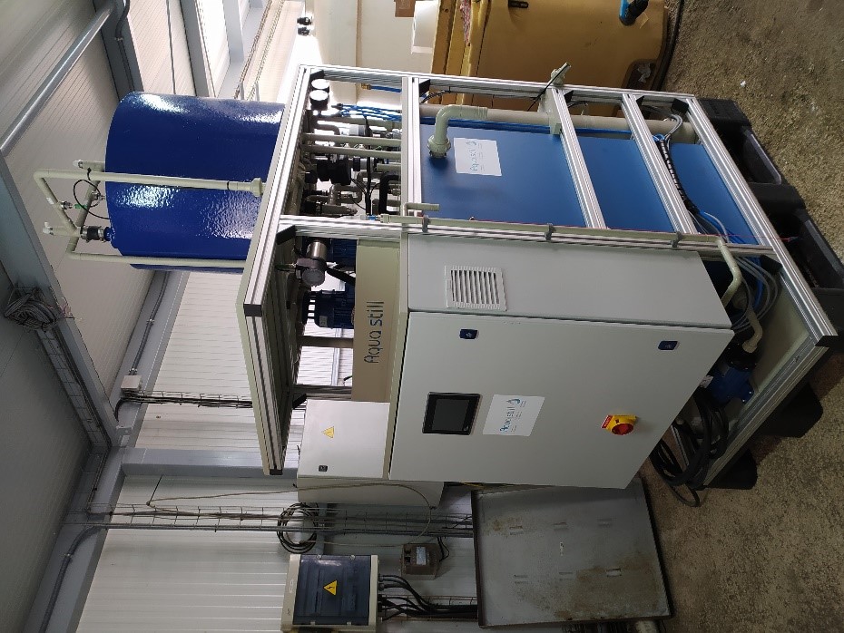
- Two spiral-wound AGMD modules from Aquastill with membrane areas of 7 m2 and 24 m2 each.
- WTS-40A and WTS-40B units from Aquaver, based on multi-effect vacuum membrane distillation technology using modules fabricated by Memsys (5.76 m2 and 6.4 m2 total membrane area respectively).
- Three spiral-wound modules from Aquastill operating in vacuum-enhanced air-gap configuration with membrane areas of 7.2, 24 and 26 m2 respectively.
Pilot Plant for Studying Combinations of Forward Osmosis and Reverse Osmosis
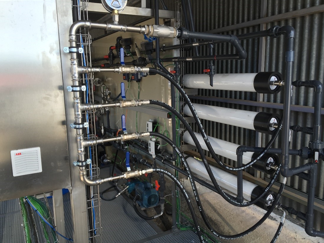
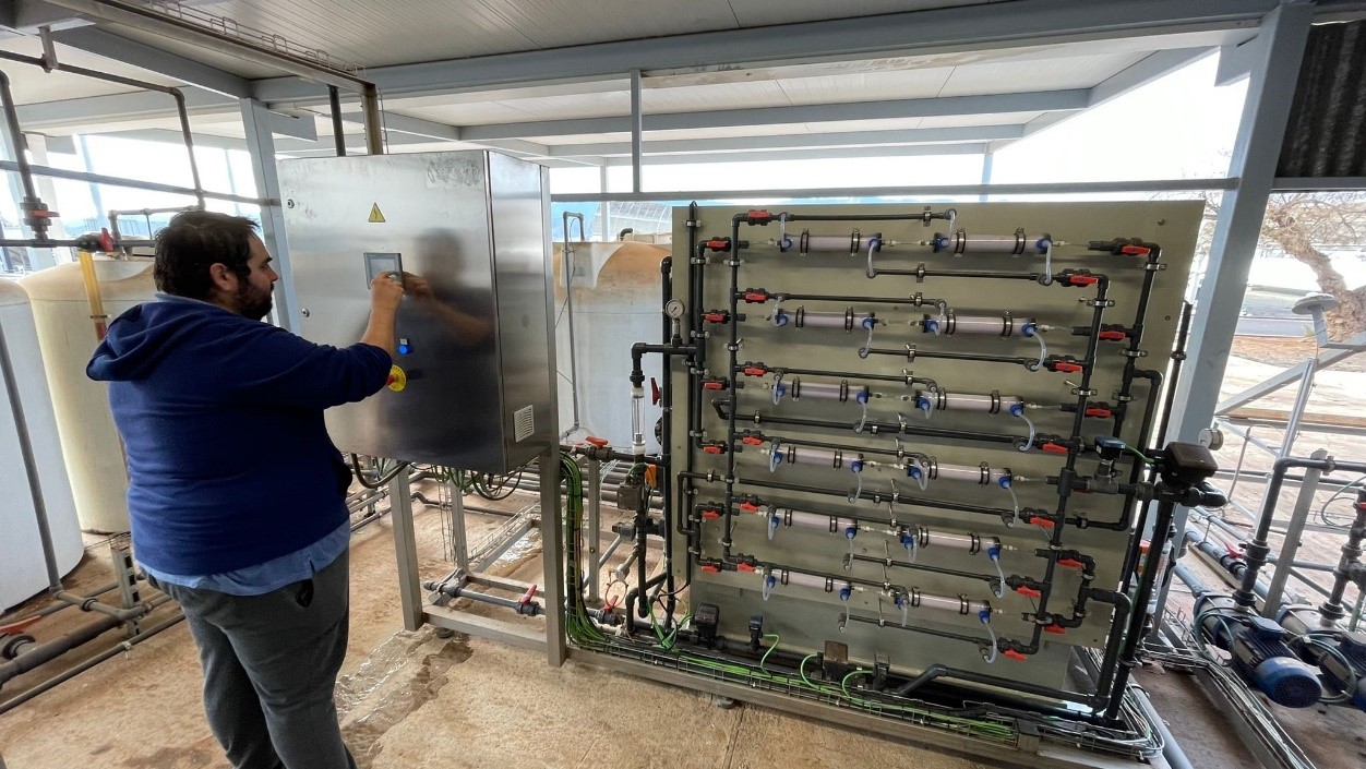
The plant has three different units (Figure 40) that can be coupled in different ways between them: (i) forward osmosis; (ii) reverse osmosis; (iii) microfiltration. The forward osmosis (FO) unit uses 12 hollow fibre modules (Aquaporin HFF02) with 0.2 mm fiber and 2.3 m2 total membrane area each one, operating in counter-current flow, inside-out, laid out in a flexible rack that allows combining them in series or parallel configuration. The nominal flow rate is 3.6 m3/h. The reverse osmosis (RO) unit has four vessels that can be connected in series or parallel, each of which hosting four membranes. The nominal flow rate is 3 m3/h and the pumping system can work at different pressures up to a maximum of 80 bar. The unit is designed so that SWRO, BWRO or NF membranes can be used. Finally, there is an MF unit with 3 m3/h nominal flow rate. The installation is completely monitored with pressure sensors, conductivity and flowmeters, and it is designed in a flexible way regarding the interconnection of the units so that FO can be used as a pre-treatment for RO, or NF can be used in combination with FO, and even the FO can be used in PRO mode using the pumping system of the RO unit.
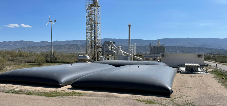
Closed-loop seawater feed system for desalination testing.
The system is composed of three storage tanks connected in series containing a total volume of 300 m3 of real seawater (Figure 41). The containers are connected to a hydraulic circuit that can supply feed water to the different desalination pilot plants at the required flow rate of each. The circuit also returns the brine and the distilled water back to the containers, so that the total mass and the salinity are conserved. A heat dissipation circuit using a compression chiller maintains the temperature constant in the containers.