IFL
The purpose of this experimental facility is to study the use of pressurized gases as heat transfer fluid in parabolic-trough collectors, evaluating their behaviour under a diversity of real operating conditions.
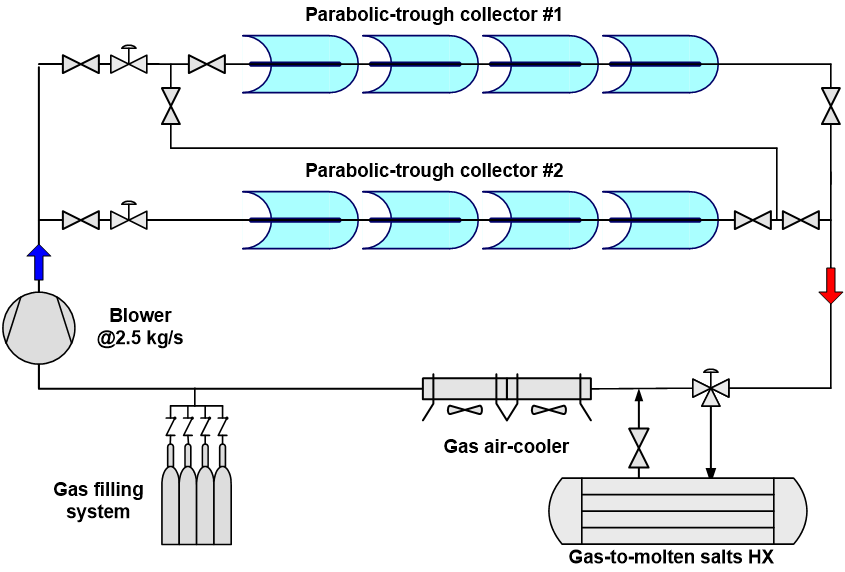
The experimental test loop (see Figure 12) is located north of the DISS experimental plant control building, which houses the equipment necessary for its control and data acquisition.
The IFL facility was originally designed to work at pressures and temperatures of up to 100 bar and 400°C, and consists of the following components:
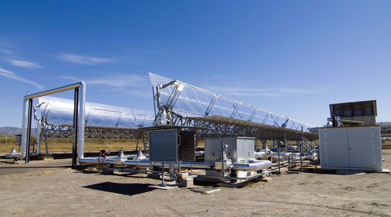
- Two East-West-oriented EUROtrough parabolic-trough collectors, each 50 m long with a 274.2-m² collector surface. The collectors are connected in series.
- A 400-kW air-cooler able to dissipate the thermal energy in the fluid delivered by the collectors. It has two 4-kW motorized fans.
- A blower driven by a 15-kW motor which supplies the gas flow rate necessary to cool the receiver tubes adequately.
- A data acquisition and control system that allows the temperature, flow rate, pressure, beam solar irradiance and humidity in the system to be completely monitored.
- Automatic control valves that allow precise, safe variation in the collector fluid feed flow rate.
- An auxiliary circuit for filling the main test loop with the gas used as heat transfer fluid.
Since testing at 400°C was successfully completed at the end of 2009, this facility was then upgraded to achieve temperatures of up to 515°C and it was connected to a two-tank molten-salt thermal storage system to test their joint capacity for collecting and storing solar thermal energy with a view to making use of them in dispatchable high-performance thermal cycles. This increase in test loop design conditions to 100 bar and 515°C made the implementation of different improvements necessary (conventional absorber tubes in one of the two collectors were replaced with advanced high-temperature tubes, stainless steel pipes were installed for the high temperature zone and changes were made in the control system).