
DESALACIÓN
CSP+D
CSP+D Test Bed: Integration of MED Thermal Desalination & Solar Thermal Power Plants
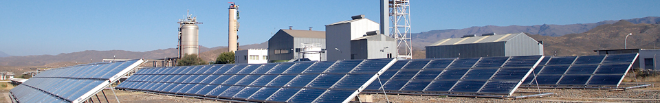
This facility is devoted to the research of the coupling between concentrating solar power (CSP) plants and Desalination (CSP+D). The testing facility is composed of two steam generators (250 kW and 500 kW) fed by thermal oil coming from a parabolic trough solar field able to deliver thermal oil with temperatures up to 400°C and an auxiliary electrical power system that raises the temperature if required. The steam generators are able to produce steam at different pressures, which allow recreating any of the typical intermediate extractions or the exhausted steam available at a turbine of a thermal power plant. The low pressure steam is obtained by making the steam from the generators to flow through two different pipe sections (12-inch diameter) equipped with control valves, which allows achieving saturated steam at two different levels: 0.074 bar/42°C (nominal flow rate of 119 kg/h, maximum flow rate of 360 kg/h) and at 0.16 bar/58°C (nominal flow rate of 195 kg/h, maximum flow rate of 360 kg/h). Both, the high- and low-pressure steam can be used as motive and entrained vapour, respectively, in a train of four steam ejectors coupled to the PSA MED plant, simulating the behaviour of a MED plant working with thermal vapour compression (TVC-MED). The steam ejectors can work in a wide range of pressure conditions for the motive steam (40 - 6 bar; 4 - 2 bar), which also makes this test bed useful for the characterization of such kind of devices. The low-pressure steam can also be condensed through two conventional air condensers without passing by the steam ejectors, with the aim of allowing research in CSP cooling topics. The flexibility of the test facility also allows the on-site evaluation of innovative dry coolers prototypes for their comparison with respect to the conventional air condensers currently available at the market.
NEP: The facility for Polygeneration Applications
Polygeneration is an integral process for the purpose of producing two products from one or several resources. In the case of solar energy, it makes use of the thermal energy from a solar field for several simultaneous applications, such as generating electricity, desalting water for drinking water supply and the rest for domestic hot water (DHW).
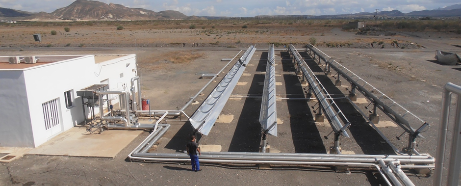
The purpose of this facility is the preliminary study of the behaviour of a parabolic trough solar field of small concentration ratio, the determination of its feasibility as a heat source in polygeneration schemes, in particular in CSP+D requiring temperatures around 200°C. The collector selected was the Polytrough 1200 prototype by NEP Solar. It has a production of 15.8 kW per module (0.55 kW/m2) under nominal conditions, with a mean collector temperature of 200°C, and efficiency over 55% in the range of 120-220°C (for 1000 W/m2 of direct normal irradiance).
The field is configured with eight collectors placed in 4 parallel rows, with 2 collectors in series within each row. This configuration supplies 125 kW of thermal energy. The temperature of the thermal oil can be up to 220°C, so different schemes for making use of the thermal energy for polygeneration can be evaluated.
Currently the solar field is also being used to generate steam for supplying the double-effect absorption heat pump coupled to the PSA MED plant.
Hybrid-cooling pilot plant
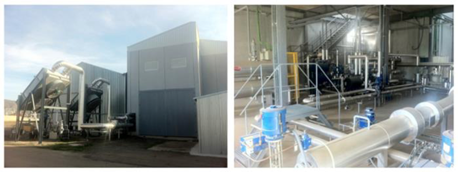
This test facility is a completed equipped pilot plant to evaluate innovative cooling systems for CSP plants. The innovative cooling system is a hybrid cooler composed of a wet cooling tower and a dry cooling tower (Air Cooled Heat Exchanger). The hydraulic circuit of the test bench has been designed to enable the testing of the wet and dry cooling separately and the series and parallel configurations. The testing facility also can compare a hybrid cooling system with a conventional air-cooled condenser.
 b)
b)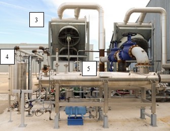
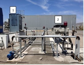
The hybrid cooling test facility consists of three circuits: cooling circuit, exchange circuit and heating circuit. In the cooling circuit, cooling water circulating inside the tube bundle of a surface condenser is cooled down through a hybrid cooler composed of an Air Cooled Heat Exchanger (200 kWth) and a Wet Cooling tower (200 kWth), functional prototypes that have been built by the French company Hamon D’Hondt. In the exchange circuit, an 80 kWth steam generator produces saturated steam (in the range of 120-300 kg/h) at different temperatures (42-60°C), which is then condensed in the surface condenser while releasing the condensation heat to the cooling water that is heated. The condensate from the surface condenser goes to a tank that supplies the water to the steam generator by a pump when needed. In the heating circuit, the AQUASOL-II large-aperture flat plate solar collector field provides the hot water to drive the steam generator. The testing facility can also compare the hybrid cooling system with a conventional Air-Cooled Condenser (335 kWth). For that, a bypass has been installed in the exchange circuit so that the steam generator can provide the steam either to the surface condenser connected to the hybrid cooler or to the Air-Cooled Condenser.