
WATER DECONTAMINATION (DETOX)
Type CPC phot reactors are built in units that can be connected in series. Each unit consists of a number of photo reactors (borosilicate glass tubes) situates in the focal point of an anodized aluminium mirror in the form of a Compound Parabolic Collector (CPC). The units are inclined 37º with respect to the horizontal in order to maximize solar photon gathering throughout a year. Also, experimental plants can be equipped with technique/system improvements with different purposes: sedimentations tanks (catalyst recovery), temperature control systems, oth-er treatments connections such as bio oxidation, ozone, etc.
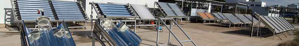
There are several experimental CPC plants in the facilities dedicated to decontaminate water with different technical characteristics, including illuminated surfaces, treatment volume, photo reactor diameter, etc. Three of these experimental plants are described below (Figure 1):
 a)
a) 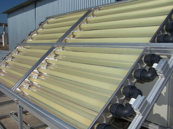 b)
b) 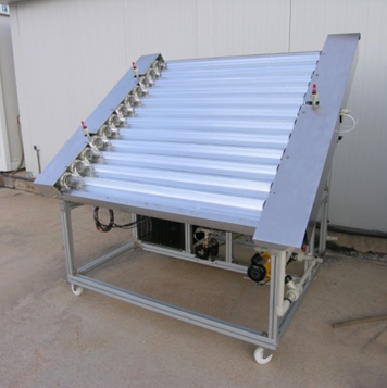 c)
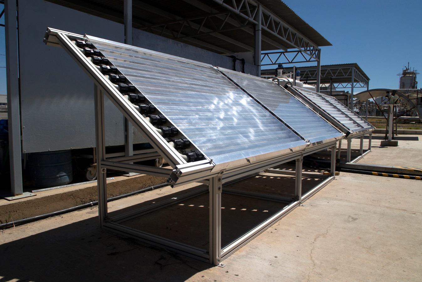
c) - CPC SOLEX photo reactor prototype (Figure1a): two twin reactors developed for specif-ic treatment applications through solar photo-Fenton. Each prototype consists of two CPC units connect to each other, with 32 mm borosilicate glass tubes, 3 m2 of illuminat-ed surface, with a total volume of 40L of which 22 L are illuminated. It also has several sounding lines that allow us to monitor dissolved oxygen (DO) and temperature (Tª).
- CPC CADOX photo reactor prototype (Figure 1b): it consists of four CPC units (50 mm tube diameter) with a total gathering surface of 4 m2, a water treatment volume of 75 L of which 45 L are illuminated. This prototype has been designed and built in order to connect it to an ozonisation system (50 L) and treatment through biological oxidation. It also has a pH, Tª, DO, H2O2, O3 and water Tª control and reactive dosage monitoring system.
- NOVO75 photo reactor prototype (Figure 1c): solar reactor prototype with different mirror set-up that allows increasing the illuminated water volume. It consists of twelve 75 mm diameter borosilicate glass tubes connected in series, with a 2 m2 illuminated surface, 74 L total volume with 68.5 L illuminated volume. It is equipped with Tª, DO and pH sound-ing lines, as well as a Tª control system and oxygen boost in water. Currently, this proto-type has been modified in order to fit in an ozonisation experimental plant.
The experimental plants based on non-solar or hybrid (connection to solar and non-solar systems) advanced oxidation treatments are described below (Figure 2):
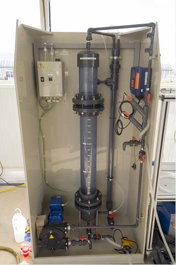
- The ozonisation reactor has a contact column with a total volume of 15 L (Figure 2a) with a generation capacity of 44 g O3/Nm3 for a 0.2 Nm3/h gas flow and modified in order to connect it to the NOVO75 photo reactor.
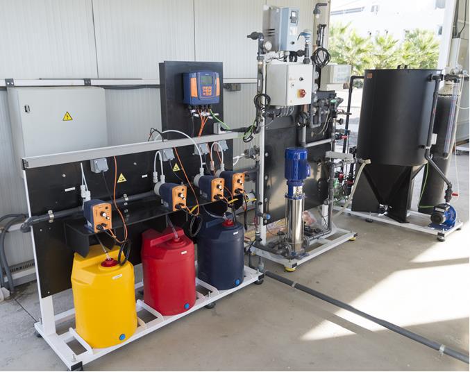
- A nanofiltration experimental plant (Figure 2b) with three membrane frames (in order to evaluate interchangeable membranes) connected in a way that it can be used in series or in parallel. Each membrane has a 5.2 m2 superficial area and can support 41 bar maximum pressure and 1.4 m3/h maximum flow. A 400 L supply tank is connected to each experimental plant. The system is completed with an automatic dosage of several reactive, among other objectives to control pH.
- A biological pilot plant with a double depuration system (Figure 2c). This system consists of a line of treatment by means of 60 L total capacity fixed-bed reactors (RLF) (three 20 L RLF) and a second line of treatment with stirred type tank reactors (RTA) with 40 L to-tal capacity (two 20 L RTA). All the reactors are inserted in the same unit. Both process-es can operate intermittent or continuously as well as independent or combinedly. pH automatic control systems and DO are incorporated in each reactor.
- Photo-electro-Fenton plant (Figure 2d): it is a system connected to 4 anodic oxidation and H2O2 generation commercial cells, which are connected to a 2 m2 CPC type photo-reactor (ten 50 mm diameter borosilicate glass tubes), 40 L total volume and 25 L illumi-nated volume.
 a)
a)
 b)
b) 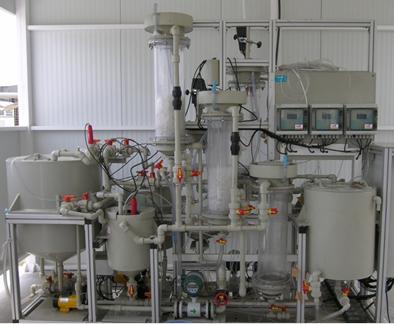 c)
c) 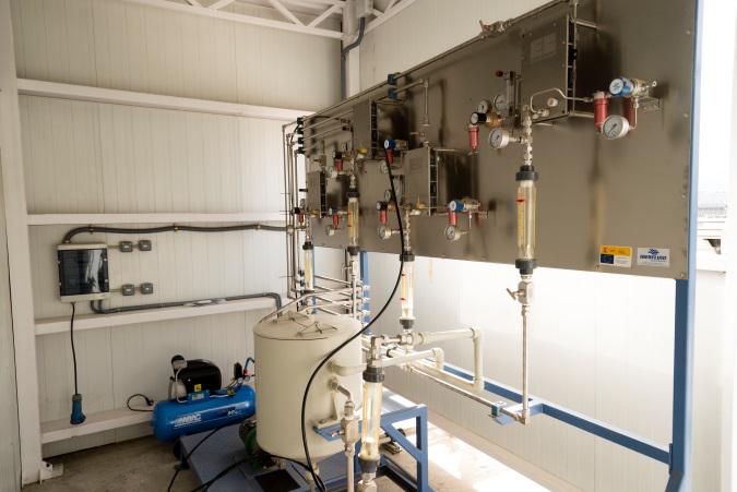 d)
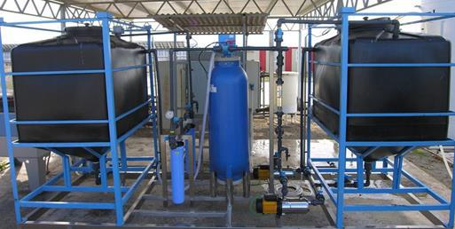
d)The facilities also count with a waste and raw water pre-treatment plant (Figure 3a) based on coagulation-floculation/filtration physic-chemical processes that allow working with a maximum of 1m3/h water flow. Such system has a sand filter and two microfilters of 25 and 5 µm, respec-tively.
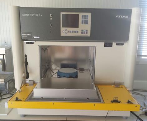
Apart from the option of escalating the described experimental plants, there is also a solar sim-ulator with xenon light in order to study decontamination in radiation and temperature-controlled conditions, at laboratory scale (Figure 3b).
 a)
a)
 b)
b)